While it is really not sqaure, it does have a lot of right angles (coompared to the ribs) so that's why I call it the 'sqaure' structure.
The square support structure is critical to the stability of the greenhouse. Some recent weather in my area had winds and gusts exceeding 50 MPH. So far this appears to be no problem. The ribs will flex nicely, taking and absorbing the wind. The square structure held firm with little sway.
Let's Begin
For starters, friction fit the square structure for now. Do not glue since there will be modifcations for the door after it is assembled.
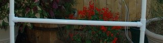
Cut four 6-foot length of 1" PVC. These four poles will be the uprights. The rear wall of the greenhouse is not a door. A horizontal cross bar will add some necessary support to that wall. To add that bar, cut two of the 6-foot length in half. Insert a 1" T into each with the short open portions of the T facing each other. Cut a 3-foot piece of 1"pipe for the horizontal bar. Insert into the T-fittings to form and 'H' shaped structure. See close up image below
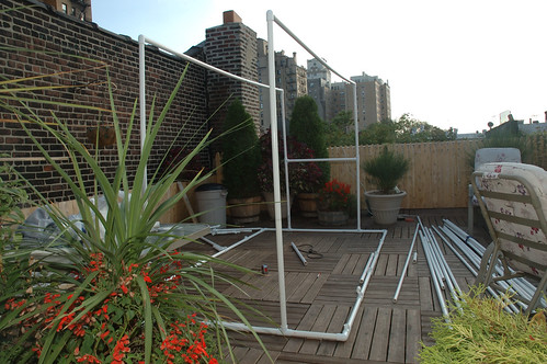
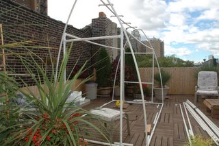
Cap the top of each up right with and elbow with the open end facing the upright on furthest opposite end of the greenhouse. Measure the distance between the uprights. When we started, this was going to be 10 feet. Due to the 'spread' in the base (discussed here in "PVC is not an exact science") this may be more like 11 feet. If you insert the 10 (or 11 ft.) lengths you will have a structure that resmebles the photo at the very top of this post.
Good so far? Let's continue.
(I've seen PVC plans that recommend inserting rigid metal pipes into the long horizontal lengths of the square structure. This seemed especially key if you want to hang planters. I'd have to agree considering they bend slightly under their own weight. Planters would seriously bow this without added support)
More Horizontal support
The front and rear walls need a 3 foot horizontal bar at the top of the uprights. This is tricky since the top of the uprights already have an elbow and that is used for the 10 foot supports. The key here is to make a small one inch cut in each upright, insert a T fitting between the ramainder of the upright and the one inch cutting, and cap with the elbows. See image below.
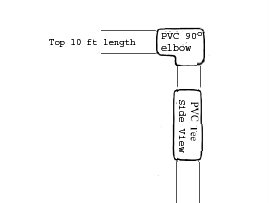
The above is a side view of one upright. Below is an image of the same from another angle.
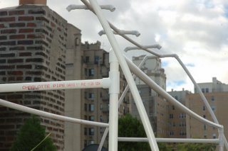
You can see how the upright has a horizontal bar at the top but also the elbow. Below is a pretty good shot of th completed structure. (My image has a few ribs already added. We'll get to that in the next step)
Tags: greenhouse, pvc, roof deck
1 comment:
great idea. Simple, cheap and effective
Post a Comment